Low latency eyes
github.com/rhoyn/teleop-camera-latency-analysis
A note before we start. This article is about measuring latency, not about solving it. Everything below is the instrument — the rig, the method, and the numbers that came out of them. The repository linked above holds the raw recordings of every experiment behind those numbers. How we actually got rhoyn’s camera link down to where it is now is a separate story, and it will be the subject of another article.
You buy your first humanoid — a Unitree G1. You unpack it, hang it on the crane, and notice the head camera is unplugged. Turns out that’s normal: most humanoids today don’t use vision at all, and balance on IMU data alone — the inertial measurement unit, the accelerometers and gyroscopes that sense tilt and acceleration. An inner ear, not eyes.

VLA models — vision-language-action: camera frames and an instruction in plain words go in, robot actions come out — are emerging but aren’t plug-and-play yet. Where a camera is fitted, it’s bolted on with no integration — like taping a RealSense to your own head and hoping your brain figures it out. Let’s plug it in and see what the robot sees.
A search turns up GR00T-WholeBodyControl and XRoboToolkit for PICO VR: install XRoboToolkit on a PICO headset and it streams the robot’s camera to you, while sending your controller and body pose back to GR00T-WholeBodyControl to drive the robot’s joints.

First, just the camera feed. XRoboToolkit-Orin-Video-Sender goes on the G1’s Orin dev board — the one you’re allowed to SSH into — wired to the camera over the robot’s back panel. But the sender and the PICO client only support one camera natively, and it isn’t the D435 already on the robot’s head. It’s the ZED Mini.

No way to make the D435 work with the stock app, so you order a ZED Mini and tape it to the robot’s head.

Plug it in, start the sender, and the headset now shows what the robot sees instead of the room around you.
But move a hand in view of the robot’s camera and the image lags behind — you’re looking at where your hand was, not where it is. Fine for waving at the robot from across the room. Not fine for precise manipulation, where you need to react to now, not to a moment ago.
You can feel the lag. You can’t yet measure it.

First idea: put a millisecond timestamp on a monitor, point both the robot’s camera and the headset’s passthrough at it, record the headset, and diff the two readings with a script.
Here is one camera frame of that panel, 25 ms exposure. The refresh is effectively instant — only the camera’s shutter is slow:
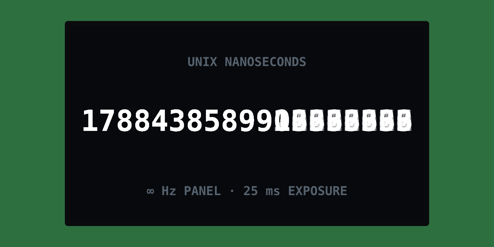
Why that band comes out blurred at all: a camera doesn’t capture an instant, it opens the shutter, exposes the sensor to photons for the whole window, and records however those photons landed. This one is a mechanical shutter rather than the digital sensor above — the mechanism differs, the exposure doesn’t need it spelled out here — but the idea is the same one driving every frame in this piece:
The leading digits are sharp because they didn’t change while the shutter was open. The rest cycled through all ten values many times over, and the camera sums whatever light arrived during that window instead of picking one instant — so every value lands on top of every other as one grey smear. The monitor doesn’t help either: it only redraws sixty times a second, so most milliseconds never reach the glass at all.
Exposure and refresh rate: two separate ways to lose the same number.
Next idea: skip the screen. Ten LEDs in a row, driven by an ESP32 at 1 kHz, encoding the millisecond count in binary — 210 states covers a full second at 1 ms resolution, read off both camera streams and subtracted.
The display isn’t the bottleneck this time — it updates every millisecond, exactly as built. The camera is: a 20–30 ms exposure is ordinary indoors, and any bit that flips faster than that averages to grey.
One frame of the diodes, same 25 ms exposure:
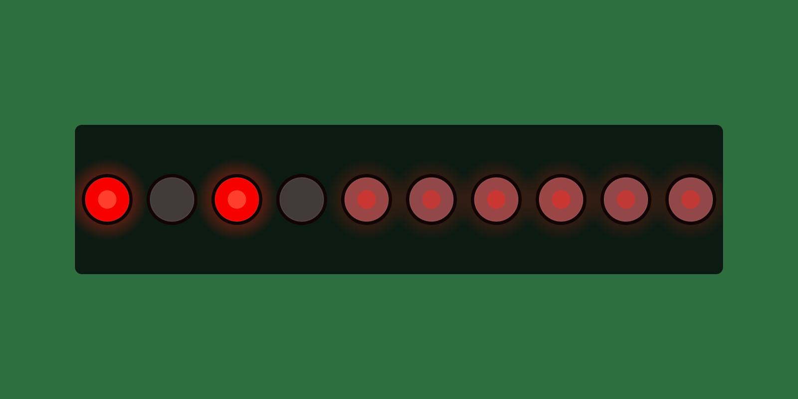
The top bits read cleanly — they don’t change during a single exposure. The bottom bits, the ones carrying the millisecond precision we actually wanted, sit frozen at half brightness: unreadable. The lowest bit flips fastest, so it washes out first, and the effect climbs the display until it reaches a bit slow enough to survive the shutter.
Give up, then? Live with the lag?
At rhoyn we measure things instead. Both attempts failed the same way: we kept trying to read a number off a display, and the exposure kept averaging it away. So stop reading numbers — track something that moves continuously, and let that same averaging work for us instead of against us.
First, a look at what we’re actually measuring:
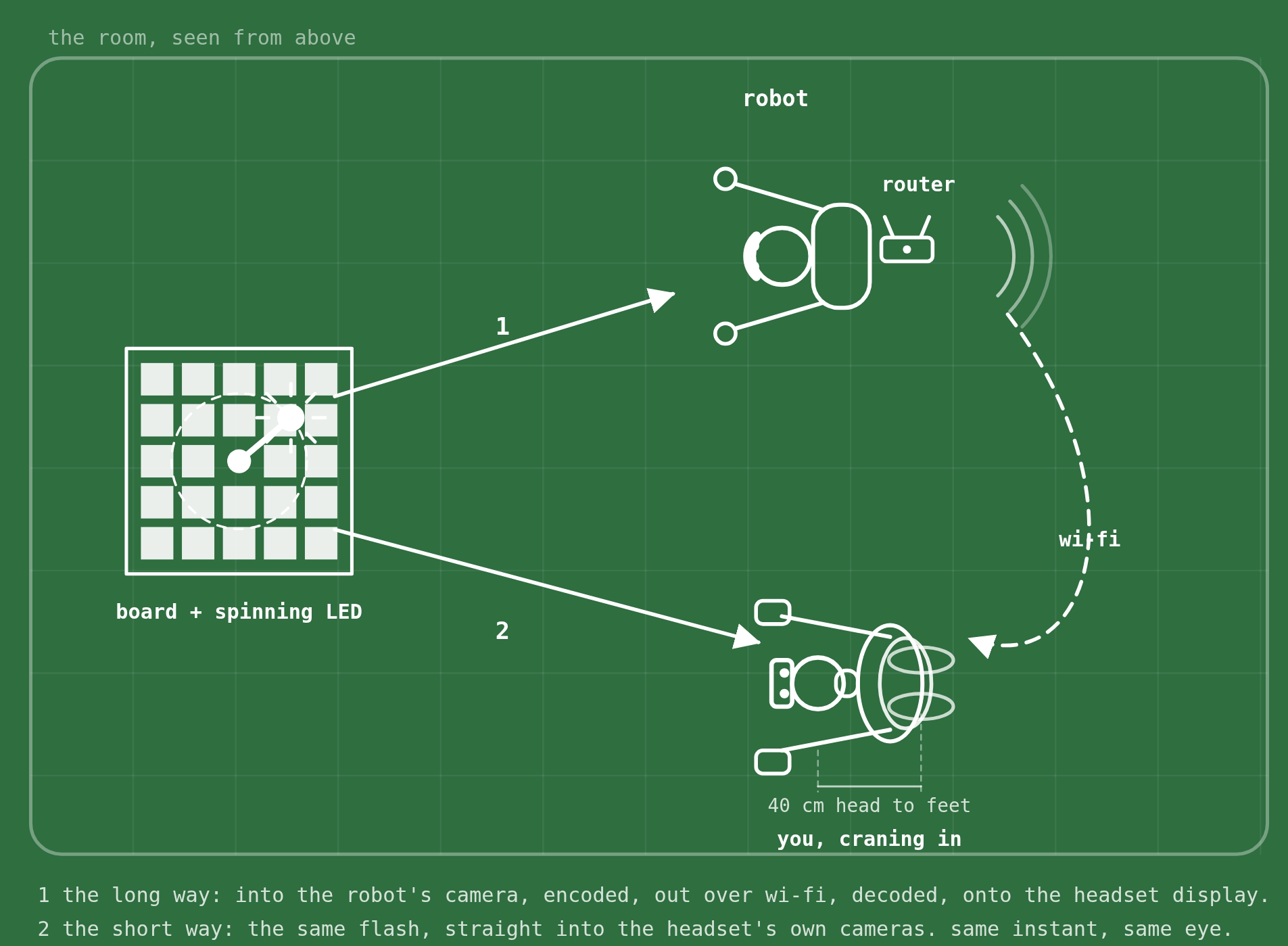
A single LED flashes once. Some of its light reaches the robot’s camera, gets encoded, sent over wi-fi, decoded, and painted on the headset display. The rest, from the same flash, travels straight into the headset’s own passthrough cameras and lands on that same display — same departure, same destination, two routes. Whatever makes the first route longer than the second is the lag we’re after, and because both rays land in the same recorded frame, we never need to synchronise a clock.

We don’t time each box in that chain individually — you can’t probe the encoder without changing what you’re timing. We time the whole path at once, from the outside, against the only reference the operator actually has: their own eyes.
The rig itself is deliberately dumb: one A0 ArUco board with an LED spinning on an arm around its centre, placed where both the robot and the headset-wearer can see it. A single headset recording then holds the same LED at least twice over — once via passthrough, once via the robot’s camera stream (three times if it’s stereo).
The big board above is the room via passthrough; the two small ones are the same board arriving through the robot’s stereo cameras. One LED, three views, one frame — and because it’s the same physical LED, everything about the views is identical except the transport between them. No clock to synchronise: the arm is the only clock in the experiment.
Here is the rig running:
For each frame the program fits the board’s pose from its ArUco markers, projects the LED into board coordinates, and records its angle. Because it’s one physical LED, every view traces the same angular speed over time — the fitted lines differ only in phase, and dividing that phase gap by the shared speed turns an angle into a time.
That clip is four panels, each one a step:
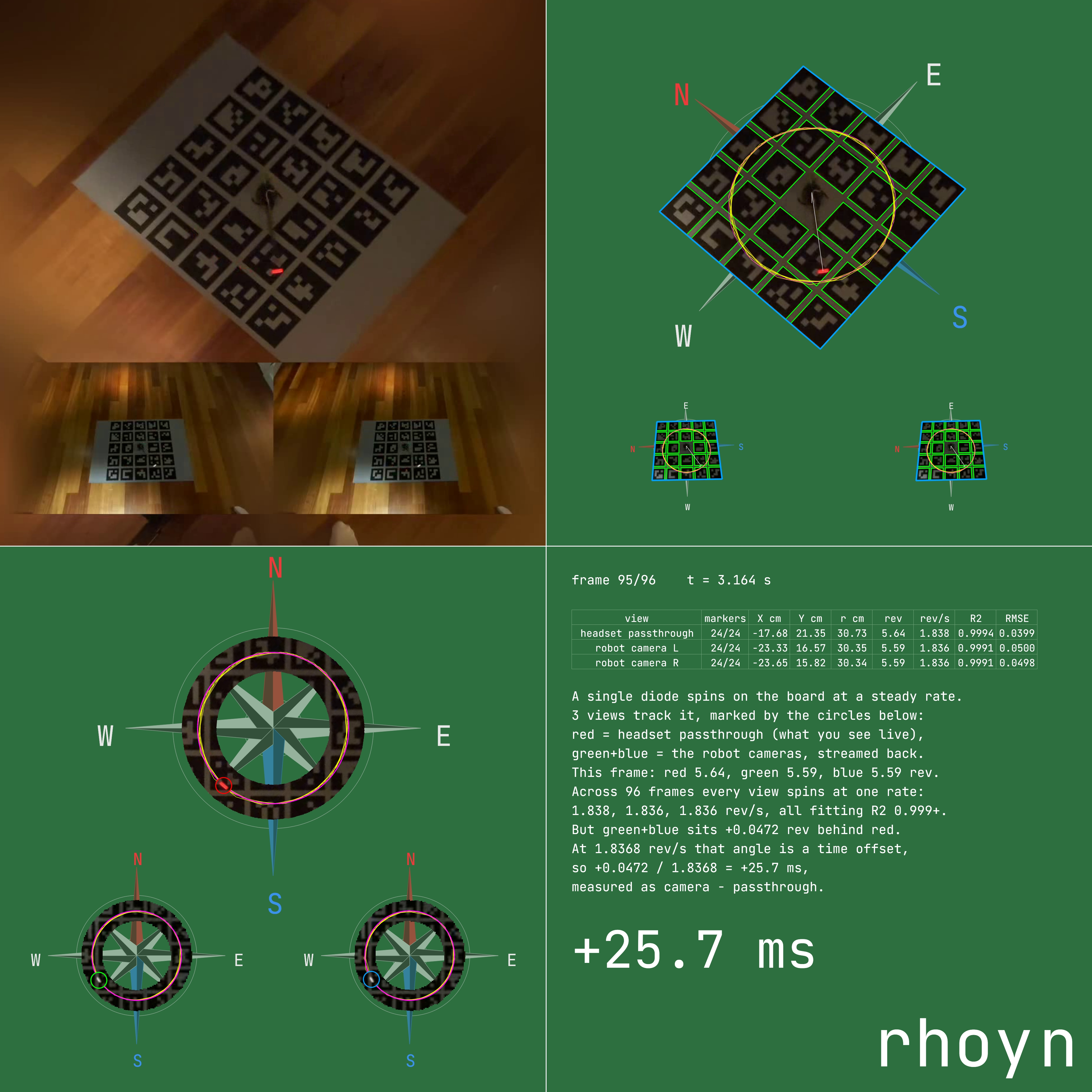
One: the recording, untouched. The large view is the headset’s own passthrough; the two strips below are the robot’s left and right cameras, streamed back and composited into the same display. One board, one LED, three views, no clock anywhere.
Two: the board’s pose, in every view. Green marks each ArUco marker found — 24 of them, in all three views; blue is the board edge reprojected from that fit, so you can see at a glance whether it’s right. The yellow circle is the LED’s orbit, the white line its current position, and everything outside the board is masked away. This is where exposure stops being the enemy: a long exposure just smears the LED into a short arc, and the middle of that arc is still a well-defined angle.
Three: the angle. The LED only ever lives on one circle, so the program crops to that ring alone. Magenta marks the orbit; the coloured circle is where each view puts the LED this frame — red for passthrough, green and blue for the robot’s two cameras. The output isn’t a pixel, it’s an angle in degrees, and a long exposure only makes that angle more precise. Frame rate stops mattering too: fitting a line across the whole clip, instead of comparing frame to frame, averages out per-frame noise and resolves well below the recording’s own frame interval — our numbers come from 30 fps video and land within a fraction of a millisecond.

That’s the whole measurement, plotted: two parallel lines of identical slope — one LED, one speed — and the horizontal gap between them is the answer, voted on by every frame in the clip. The arm’s speed doesn’t need to be known or held constant; it’s measured fresh from each clip. Nothing here is calibrated, trusted, or timestamped.
What comes out is one signed number in milliseconds (camera minus passthrough), plus this four-panel video showing exactly how it was built:
Four: the arithmetic, written out. One row per view — markers found, LED position, revolutions, fitted speed in rev/s, and the R²/RMSE that say whether a straight line was the right fit — then the result in words. Here all three views turn at 1.838, 1.836 and 1.836 rev/s, and the robot’s two cameras sit 0.0472 rev behind passthrough: +25.7 ms, camera minus passthrough. This clip is the XRoboToolkit + ZED Mini stack the article started with, caught in the act.
Results
Eight recordings on each stack, same rig, same program, signed as camera minus passthrough — positive means the robot’s camera view is that far behind what the headset already shows you live:
| # | rhoyn + stock D435 | XRoboToolkit + ZED Mini |
|---|---|---|
| 0 | −4.3 ms | +25.7 ms |
| 1 | −2.4 ms | +31.7 ms |
| 2 | +6.9 ms | +40.5 ms |
| 3 | −2.7 ms | +39.7 ms |
| 4 | +5.5 ms | +41.2 ms |
| 5 | −1.8 ms | +28.7 ms |
| 6 | −3.8 ms | +35.0 ms |
| 7 | +3.1 ms | +35.6 ms |
| median | −2.1 ms | +35.3 ms |
| mean | +0.1 ms | +34.8 ms |
The two sets never overlap: rhoyn runs −4.3 to +6.9 ms, straddling zero — no measurable difference from the headset’s own passthrough. XRoboToolkit + ZED Mini runs +25.7 to +41.2 ms, every clip behind every rhoyn clip. Pairing all 64 combinations and taking the median gap: 34.7 ms, measured by the same instrument on the same board.
Here is that first row, run 0, for rhoyn: −4.3 ms, camera minus passthrough — run through the same four panels above.
Everything is open sourced — the measurement program, the printable board, the spinning arm’s OpenSCAD source and STLs, and its bill of materials. MIT licensed, at github.com/rhoyn/teleop-camera-latency-analysis.
Play with it
Everything above is in one instrument here, nothing switched off. R/F moves the camera latency, T/G the control latency, arrow keys move both. Y cycles what’s on the floor — nothing, the monitor, the LED word, the marker board — and H toggles the robot’s camera between stereo and single view. Push the camera to 200 ms and try to place a hand exactly where you meant to.
rhoyn is a humanoid data company. We build bleeding-edge teleoperation software and use it to collect high-quality datasets in diverse environments, then provide them to the teams training humanoid robots.
github.com/rhoynIf you need high-quality humanoid teleoperation datasets, contact us hello@rhoyn.com